| Introduction |
| Axial Force Control and Temperature Gap Compensation |
| Controlling Axial Force |
Axial force control is an important feature for many applications, from ensuring that contact is maintained between the geometry and sample during compression control to keeping solids taut in tension control. This topic describes how axial force control operates, explains the axial force control parameters, and cites specific conditions to apply when testing materials requiring axial force control.
Axial force control should be used when materials expand (and/or contract) or slip during testing. If changes in volume occur, the material will either be subject to a normal stress field or shrink away from the testing geometry; either situation will cause errors in the results. Generally, volume changes within a material occur by changes in temperature, solvent/moisture loss, or when the material gels or cures. In order to convey the use of axial force completely, the remainder of this section will associate the volume change of a material with a change in temperature, described by the coefficient of expansion. The most widely used test mode to control axial force is in the oscillation mode with a temperature ramp. Axial force control is also used to maintain a static force on the sample to avoid unloading of the sample during oscillation testing.
The axial compliance of the ARES-G2, RSA-G2, DHR, and AR is only a few tenth of microns per Newton. The normal force transducer senses volumetric changes of the sample. A volumetric change entraining a vertical expansion of a few microns, assuming the material is stiff enough to translate the resultant force, may cause the normal force transducer to go into an overload condition. If axial force control is active, the normal force transducer will detect the change in normal force and command an adjustment of the head position i.e. increase or decrease the gap to hold the actual normal force constant.
ARES-G2 and DHR behave differently during axial force control when the thermal compensation coefficient (Gap Hold) in the geometry form is checked. On the ARES-G2, the Gap Hold function is deactivated as soon as the axial force control is activated. On the DHR, the thermal gap compensation (Gap Hold) remains active when axial force control is active as long as the axial force stays within the lower and upper band of the window defined by the current axial force and the force sensitivity.
Axial force control can be enabled/disabled and set in the Axial force section of the Instrument Control panel (maintaining the specified conditions prior to the test), as well as in a procedure. Axial force adjustment conditions set in the Instrument Control panel can be inherited and used during the test procedure, if desired.
Axial force control prior to the start of a test procedure is set in the Axial force section of the Control panel. Activate axial force control after loading the sample, but before enabling temperature control. Select the Experiment tab > Controls ![]() , then select Axial Force.
, then select Axial Force.
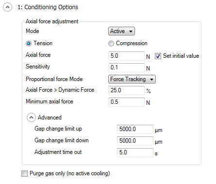
Axial force control settings for RSA-G2, ARES-G2, and DHR for linear and rotational oscillation testing:
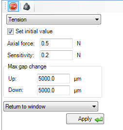
The axial force control panel only allows you to set a constant force. Advanced axial force control algorithms that may be needed during testing must be set in a procedure conditioning step.
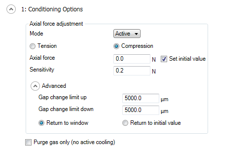
In order to control axial force during a procedure, the axial force control must be enabled in a procedure. If axial force adjustment is not activated in the procedure conditioning step, axial force control is disabled at the start of the procedure. Insert a Conditioning > Options step and select the Axial Force Adjustment option in order to activate this feature. When axial force is not active prior to the test start, there is no need to add a conditioning step to disable the axial force control.
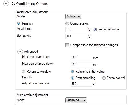
For many testing scenarios, axial force needs to be active prior to and during a procedure. In this case, the axial force needs to be activated and set in the Control panel and in a procedure conditioning step. The adjustment conditions prior to the start of the test can be inherited by the procedure. Different control conditions can be set if desired in the procedure. Use Inherit for the force adjustment option only if you want to keep the same constant force during the complete test procedure. If a different force, or advanced axial force control algorithms need to be set, switch the axial force adjustment to Active and set the desired control parameter.
The axial force parameters inherited from the Control panel or set in a procedure conditioning step can be turned off during the procedure by adding a Conditioning step and selecting Disabled for the Axial force mode.
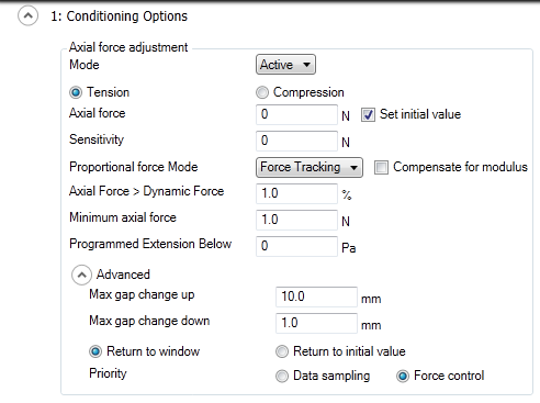
In DMA mode, the axial force and the dynamic force are measured by the same normal force sensor. Therefore, the axial force must be adjusted prior to the measurement of the individual dynamic point. In order to avoid too much stretching or compression of the sample, the axial force is adjusted proportional to the dynamic force (force tracking mode). When Compensate for modulus is selected, the static force is based on the estimated modulus rather than the dynamic force. This is necessary when Auto strain adjust is activated and the strain changes during the test. The algorithm extrapolates the value of the modulus at the new temperature based on the previous modulus change. The new dynamic force is calculated from the estimated modulus for the applied strain. The new static axial force is then determined from the new dynamic force based on the Axial Force > Dynamic Force criterion.
The Programmed Extension Below, when used, applies when the measured modulus falls below a threshold value. When the modulus crosses the threshold value, the axial force control is disabled/enabled because the sample has become too soft/stiff for the axial force control operation. The sample is extended (to avoid buckling or squeezing) by changing the gap based on the material expansion coefficient (set in the Options > Material properties). If this value is zero, the extension is based on the applied gap change before the Programmed Extension Below criterion came into effect.
The axial force control on the DHR is based on the same algorithms as the ARES-G2/RSA-G2. The instrument always operates in Data sampling priority mode with an Adjustment time out for the axial force adjustment control.
